Multiple Powered Subwoofers
Take one already-processed subwoofer feed and distribute it to several powered subs, with a dedicated front-panel level control for every feed.

Modular Bass & Subwoofer Signal Distribution
One line-level bass or subwoofer feed in. Eight independently controlled mono feeds out—for amplifier inputs or powered subwoofers. BD-CORE Revision E is the analog heart of the first five builds.
Now Building · Revision E
BoomDookie sits between one line-level bass source and the equipment that drives your subwoofers. Feed it from a DSP, crossover, mixer, preamp, or processor; it gives you eight separately controlled mono RCA feeds for downstream amplifier inputs or powered subwoofers.
Take one already-processed subwoofer feed and distribute it to several powered subs, with a dedicated front-panel level control for every feed.
Send one line-level output from a DSP, crossover, mixer, or AV processor to multiple subwoofer-amplifier inputs without building a tree of Y-cables or daisy chains.
Deliver the same bass program to several amplifier channels or locations while trimming each feed at the rack. Downstream gear can still handle zone-specific delay, EQ, and limiting.
Present the same source to several amps, powered subs, or processing chains for setup, matching, comparison, and documented prototype testing.
Important: BoomDookie is a line-level signal distributor—not a power amplifier. It does not connect directly to passive speakers and it does not make speaker power. The first five units are prototypes; these are intended routing uses, not published performance claims.
BoomDookie is a modular bass and subwoofer signal-distribution platform. The core hardware is BD-CORE — an eight-channel mono, line-level distribution board that takes a single RCA input and fans it out to eight independent, protected RCA outputs.
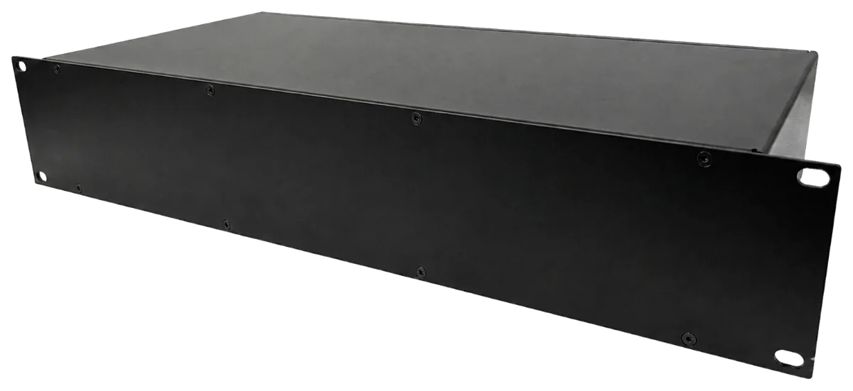
This eight-channel, internally powered 2U unit is the machine we are making now. The first run is planned as five CH2-10 prototypes for assembly, audio testing, thermal validation, and real-world use.
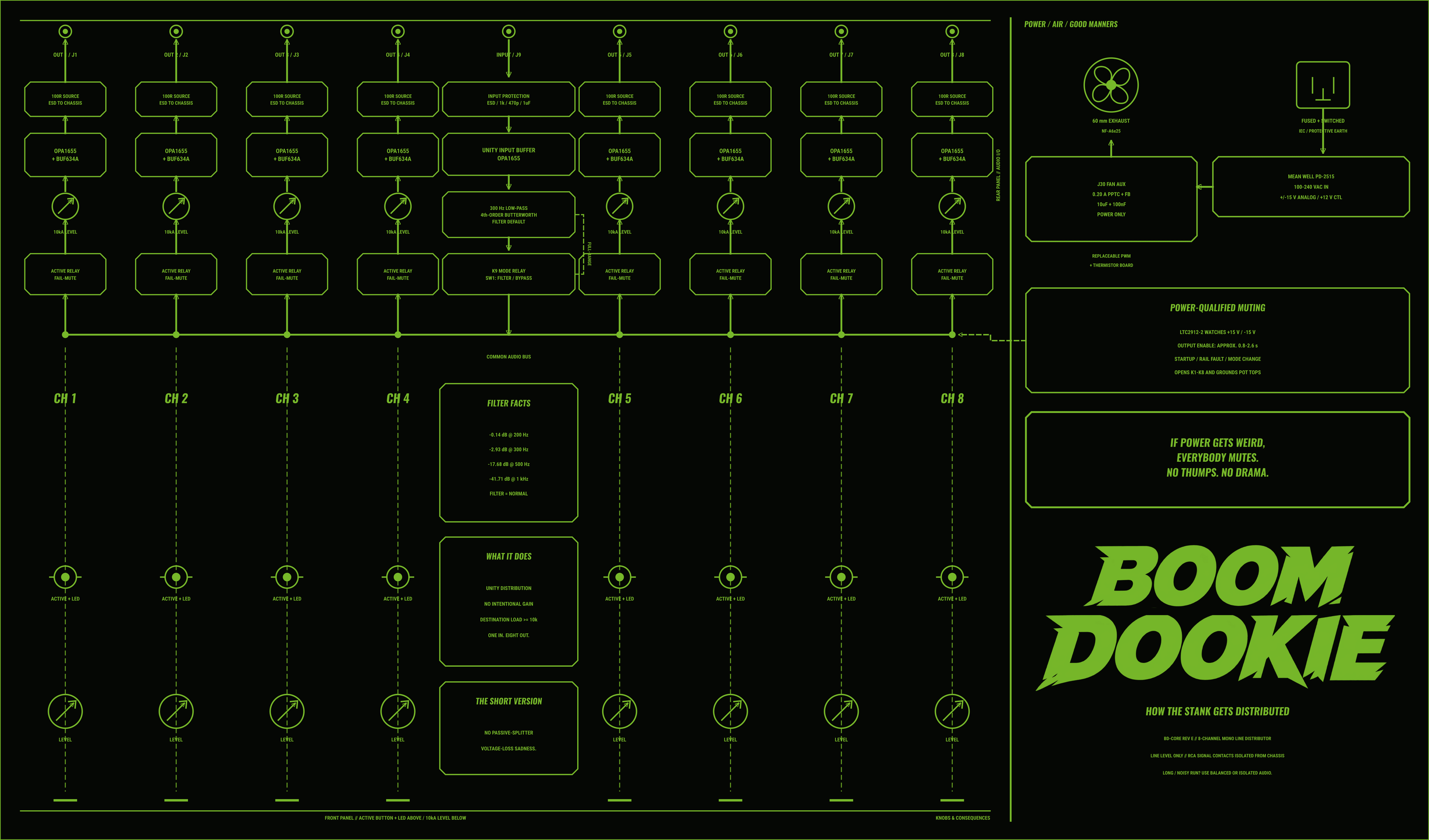
J1–J8 are eight independent mono coaxial outs. One RCA per channel — never stereo pairs. J9 is the separate line-level input.
A selectable fourth-order Butterworth low-pass with a nominal 300 Hz corner. FILTER is the default; SW1 selects FILTER or BYPASS.
Eight repeated channels on OPA1655 + BUF634A composite output drivers, each with 100 Ω cable isolation and low-capacitance ESD protection.
Both analog rails must be healthy before the output-relay supply is enabled. Power loss fails muted; filter changes force a short all-channel mute.
Every channel has separate headers for remote level control and its illuminated switch, keeping all eight front-panel controls modular and serviceable.
All nine cable-facing protectors drain to a dedicated chassis bus and single plated bond point instead of dumping the first transient into audio ground.
F1 and F2 protect the analog supply rails with fitted 0.75 A hold, 24 V Littelfuse PPTCs that reset after the fault is removed.
Revision E adds J30, a protected and filtered two-pin 12 V auxiliary output that powers the enclosure fan directly from BD-CORE.
This current Revision E visualization brings the enclosure, core board, selected controls, connectors, power hardware, and assembly sequence into one continuous feature tour.
This is a development render—not the final production film or a photograph of a completed unit. It documents the work so far and will be replaced as the model, wiring, artwork, and animation are refined.
The film will be held temporarily in this browser tab—not saved to your gallery or Downloads.
One blue line-level input enters BD-CORE, passes through the selectable low-pass path, and becomes eight independently controlled mono feeds.
This is not concept art. These renders come directly from the current Revision E KiCad board—the same six-layer design prepared for the first five units. Select any view to inspect the components up close.
Revision E supersedes Revision D for the first five fabrication and assembly work. The updated renders now show the fitted Littelfuse 1812L075/24DR resettable protectors at F1 and F2, and the board adds J30 as a protected, filtered two-pin 12 V fan auxiliary output.
Not a parts-bin fantasy. These are the selected controls, connectors, and power hardware going into the first five BoomDookie units.
A compact open-frame dual-rail supply selected specifically for BD-CORE's analog power requirements.
24 W · +15 V / −15 V · 0.8 A per rail Verified datasheet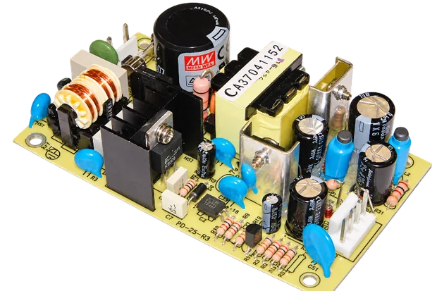
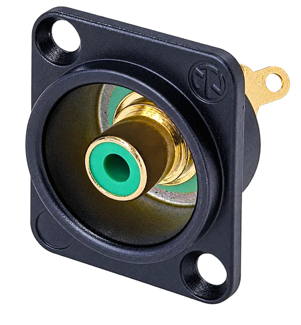
A single blue D-series RCA input sits among eight green isolated NF2D-5 mono outputs.
NF2D-5 output drawing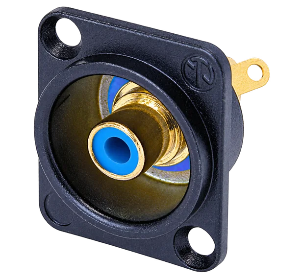
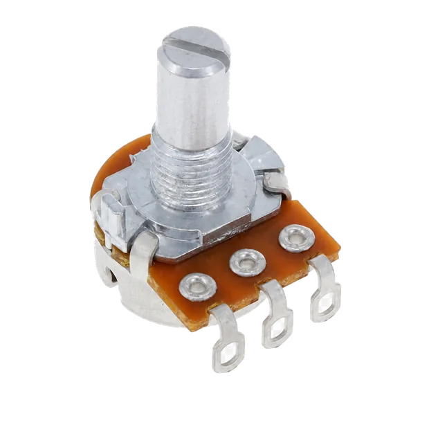
Each output gets a 10 kΩ audio-taper potentiometer beneath a green anodized-aluminum knob with a clear white index line.
Potentiometer datasheet Knob drawing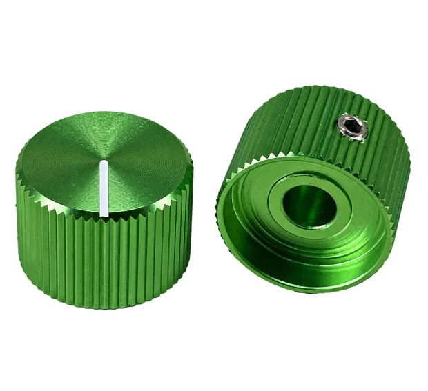
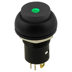
One alternate-action, green-illuminated button per channel operates and identifies its fail-muted output.
PB5L · IP67 Verified datasheet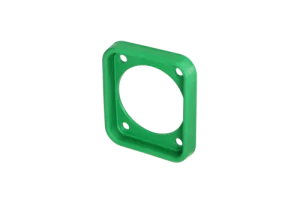
Eight green SCDP-FX-5 gaskets and one blue SCDP-FX-6 input gasket sit between the rear panel and the black NF2D housings, sealing and color-coding the nine RCA positions.
8 × SCDP-FX-5 · 1 × SCDP-FX-6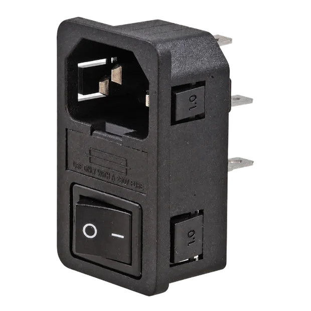
The fused, switched Adam Tech C14 inlet mounts in a bonded 1.0 mm adapter plate because the CH2-10's 3.175 mm rear panel is too thick for the inlet's snap-in body. Inside the rack, the mains zone and open-frame supply receive a dedicated finger-safe guard.
IEC-GS-1-100 · fused · switched Verified datasheetReference images show selected prototype parts. Original BoomDookie build photography will replace catalog imagery as assembly begins; the selected 2U enclosure appears below.

Open the callouts to follow the physical build from its single blue input to the protected analog core and eight green outputs.
The centered, visually distinct coaxial input is the only program feed entering the system.
The six-layer analog board handles filtering, eight repeated output channels, muting, protection, dedicated control headers, and the protected J30 fan auxiliary output.
Every output receives its own level potentiometer and illuminated alternate-action control.
Eight independent mono RCA feeds leave through isolated D-series output connectors—one connector per channel.
The fused and switched IEC entry, open-frame dual-rail supply, bonded chassis, and internal guard form the mains side of the build.
The core board and Mean Well supply mount on standoffs; TP1–TP10 remain available for bring-up, and the exact fan, feet, controls, connectors, and removable enclosure fasteners are represented in the assembly model.
The internal harness is being laid out as part of the mechanical assembly model so the first prototype can be wired cleanly, serviced channel by channel, and photographed honestly.
Each rear RCA connection is planned as a twisted green signal conductor and black ground conductor from its JST header to the soldered jack connection.
All three conductors for each P160KNP potentiometer are planned as one twisted bundle, keeping the eight front-panel level-control harnesses orderly and easy to trace.
Each illuminated pushbutton's four-pin JST harness separates into two twisted pairs: one pair for the switch contacts and one pair for the green LED.
Red and black power conductors route through the Molex connection to the Mean Well PD-2515, kept apart from the low-level signal bundles wherever the enclosure allows.
Harness colors and routing are the current assembly plan. Final pin order, wire gauge, lengths, strain relief, tie-down locations, and mains clearances will be checked against the physical first unit before the plan is treated as production documentation.
Revision E is the current fabrication and assembly baseline. This log separates completed design work from the proof still owed by assembled hardware. Last updated .
Revision E supersedes Revision D with the protected, filtered J30 fan auxiliary output. The eight-channel signal path and mechanical baseline remain unchanged, and the updated fabrication and assembly package is prepared.
The dimensioned CH2-10 assembly model now includes the exact board, Mean Well supply, Noctua fan, controls, NF2D/SCDP rear connectors, IEC adapter, feet, standoffs, fasteners, final registered panel and lid artwork, and the planned twisted-pair harness routes.
Power-rail verification, supervised mute behavior, control wiring, and all eight signal paths will be checked before full enclosure integration.
Frequency response, noise, crosstalk, mute timing, thermal behavior, and finished-build photography will be published here as measured—not predicted. The oscilloscope, multimeters, supporting bench gear, wiring, and test setup will be photographed so readers can see how each result was obtained.
The full-width CH2-10 version is the priority and the only model this page is presenting in detail.
After the eight-channel units are proven, the next direction is a four-channel version in a smaller enclosure with an external power supply. Details stay open until the current build earns them.
Build interest, progress updates, technical questions, or low-frequency collaboration—choose the signal you want to send.
This first version prepares a structured email directly on your device. No information is uploaded or stored by this page, and nothing is sent until you approve it in your email app.
A direct subscription form will replace this handoff after the public mailing workflow is configured.